Alteon MLT Distribution Algorithm
Posted On Jul 21, 2008 at at 2:05 PM by DophiMulti-Link Trunk (MLT) is a link aggregation protocol designed by Nortel. This technology groups multiple physical links into one logical link. It provides fault tolerance and high speed links between routers, switches, and even servers. But, this time, I would like to only focus on how MLT increases the bandwidth and distributes traffic into multiple physical links.
According to the official document from Nortel, Alteon uses the algorithm as below
hash_idx = (A xor B)
port = (lower 6 bits of hash_idx) mod x
The x is the number of active ports within the trunk group. The parameters A and B are assigned for different types of frames or packets. There are four different scenarios Alteon uses to distribute traffic:
• For Layer 2 forwarding:
A = lower 16 bits of destination MAC address
B = lower 32 bits of source MAC address• For L2 forwarding of IP frames:
A = lower 16 bits of source IP address
B = lower 32 bits of source MAC address• For L3 forwarding:
A = lower 32 bits of destination IP
B = lower 16 bits of source MAC• For L4 trunking (traffic towards the real servers in SLB and WCR):
A = lower 32 bits of source IP
B = lower 16 bits of destination MAC
To prove this algorithm and improve the bandwidth between ERS5500 and Alteon, I setup a lab including Alteon 3408, two clients, and two servers with the topology below. I group only two physical links into each MLT because this makes the result of this lab can be identified easily with "mod 2" calculation.
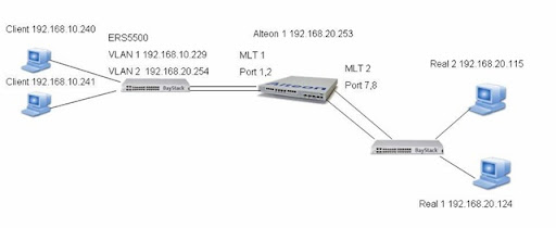
Virtual IP: 192.168.20.102, 192.168.20.103
To make sure each VIP shares the same MAC address, dump ARP table from Alteon
>> Address Resolution Protocol# dum
IP address Flags MAC address VLAN Port Referenced SPs
--------------- ----- ----------------- ---- ------ ----------------
192.168.20.100 P 4 00:16:ca:51:72:0e 1-4
192.168.20.101 P 4 00:16:ca:51:72:0e 1-4
192.168.20.102 P 4 00:16:ca:51:72:0e 1-4
192.168.20.103 P 4 00:16:ca:51:72:0e 1-4
192.168.20.115 00:0e:a6:8f:73:9c 1 8 empty
192.168.20.124 00:0e:a6:8f:72:6f 1 7 1-4
192.168.20.253 P 00:16:ca:51:72:00 1 1-4
192.168.20.254 00:14:0d:d6:a4:41 1 1 1-4
Scenario 1: L2 Forwarding of IP frames
- Setup the interface IP of VLAN 2 of ERS 5500 as a default gateway for Real 1 and 2.
- Change the MLT mode to Advanced (ERS5500 uses source and destination IP address as the index of algorithm) on ERS5500.
- Every IP address of clients and servers are one bit difference.
- Use two clients to access HTTP service of VIP 192.168.20.102.
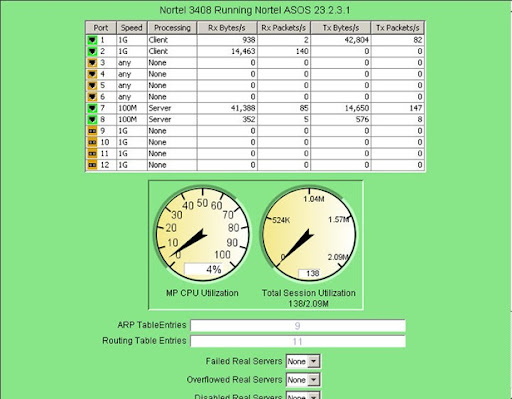
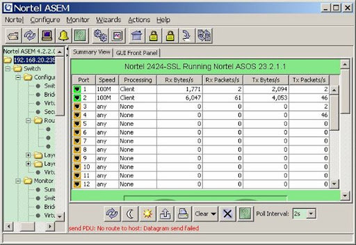
Step 1: Use client A 192.168.10.240 to access VIP 192.168.20.102, the traffic generated only on port 1 TX as this screen shot below.

Step 2: Stop the session generated at Step 1, use client B 192.168.10.241 to access the same VIP. The result is the same as what I got at Step 1.
Step 3: Stop the session and use client A 1921.68.10.240 to access VIP 192.168.20.103. Alteon starts using port 2 to send response packets from servers back to client.

Step 4: Stop client A, use client B 192.168.10.241 to access VIP 192.168.20.103. I get the same result as Step 3.

Test Result: Alteon follows the L2 forwarding of IP frame algorithm and distribute traffic by source IP and MAC address.
Scenario 2: L3 Forwarding
- setup the interface IP of Alteon as a default gateway for Real 1 and 2 (This makes response packets from servers be routed via Alteon).
- Every setting is the same as Scenario 1.
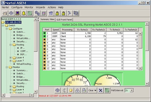
Step 1: Use client A 192.168.10.240 to access VIP 192.168.20.102 and get the result as below; packets are sent via port 1.
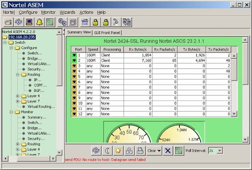
Step 2: Use client B 192.168.10.241 (one bit different with client A) to access VIP 192.168.20.102. Alteon starts using port 2 instead of 1 to send traffic.
Step 3: Use client A 192.168.10.240 to access VIP 192.168.20.103. The response packets are sent via port 1 TX.

Step 4: Use client B 192.168.10.241 to access VIP 192.168.20.103, Alteon sends packets via port 2.
Test Result: Alteon distributes packets in a MLT group based on L3 forwarding algorithm. The distribution changed when destination IP address is changed.
Compare with the two results from different scenarios, Alteon change its distribution behaviors for L2 forwarding of IP frames and L3 forwarding. In some cases, this potentially causes MLT distribution uneven when a customer uses only one VIP to make load balancing and there is no other VLANs on Alteon as Scenario 1 in a real world.
ERS5500 provides two modes for MLT distribution, Cisco IOS also provides it even a command to trace traffic in a Etherchannel group, and Alteon module of IBM Blade Center provides tunable MLT as well. I don't understand why Nortel never want to change it or provide a tunable MLT on Alteon to fulfil some cases.
Note:
- The MLT never doubles the throughput of two links. As the test result, Alteon can have maximum 1.6Gb throughput on a MLT connected to ERS 5500 and 1.2Gb to Cisco 3750.
- By default, Cisco Etherchannel never distributes traffic on two links unless we issue commands to enable it. Command:port-channel load-balance