Alteon Hot-Standby Redundancy Configuration - Part 2
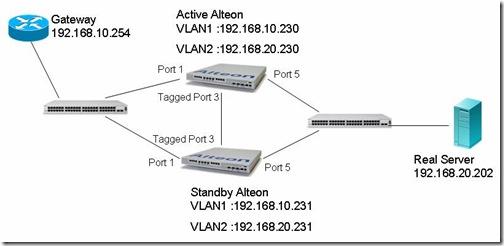
Posted On Oct 3, 2008 at at 4:47 PM by DophiThis lab bases on the previous note "Alteon Hot-Standby Redundancy Configuration - Part 1". The topology of previous note is only one VLAN on both Alteon. Hot-Standby Redundancy also can be implemented on the topology that clients and servers locate in different VLANs.
Lab 2: Multiple VLANs implementation
Active Alteon:
1. Change port 3 to be a tagged port
>> Main# /c/port 3/tag en
Current VLAN tag support: disbled
New VLAN tag support: enabled
1. Create VLAN 2 for the server farm and add port 3 and 5 as members:
>> Main# /c/l2/vlan 2/def 3 5
VLAN number 2 with name "VLAN 2" created.
Port 5 is an UNTAGGED port and its current PVID is 1.
Confirm changing PVID from 1 to 2 [y/n]: y
Current ports for VLAN 2: empty
Pending new ports for VLAN 2: 3
Current ports for VLAN 2: empty
Pending new ports for VLAN 2: 3 5
Current ports for VLAN 2: empty
Pending new ports for VLAN 2: 3 5
2. Add an interface IP for VLAN 2:
>> VLAN 2# /c/l3/if 2
>> IP Interface 2# addr 192.168.20.230
Current IP address: 0.0.0.0
New pending IP address: 192.168.20.230
Pending new subnet mask: 255.255.255.0
>> IP Interface 2# vlan 2
Current VLAN: 1
New pending VLAN: 2
>> IP Interface 2# en
Current status: disabled
New status: enabled
3. Create a VIR for interface 2:
>> Main# /c/l3/vrrp/vr 3
>> VRRP Virtual Router 3# addr 192.168.20.232
Current IP address: 0.0.0.0
New pending IP address: 192.168.20.232
>> VRRP Virtual Router 3# if 2
Current interface number: 1
New pending interface number: 2
>> VRRP Virtual Router 3# vrid 3
Current virtual router ID: 1
New pending virtual router ID: 3
>> VRRP Virtual Router 3# sha dis
Current sharing: enabled
New sharing: disabled
>> VRRP Virtual Router 3# en
Current status: disabled
New status: enabled
>> VRRP Virtual Router 3# apply
4. Change the real server IP to a new one:
>> Main# /c/slb/real 1/rip 192.168.20.202
Current real server IP address: 192.168.10.202
New pending real server IP address: 192.168.20.202
>> Real Server 1 # apply
Standby Alteon:
Dump the configuration script from active switch and modify any necessary commands. Copy and Paste the script to standby switch.
The following script is the configuration of active switch of this example.
script start "Nortel Application Switch 3408 E" 4 /**** DO NOT EDIT THIS LINE!
/* Configuration dump taken 0:30:53 Fri Oct 3, 2008
/* Configuration last applied at 23:27:54 Thu Oct 2, 2008
/* Configuration last save at 23:30:37 Thu Oct 2, 2008
/* Version 24.0.2, Base MAC address 00:1b:25:78:e1:00
/c/port 3
tag ena
/c/port 5
pvid 2
/c/l2/vlan 1
learn ena
def 1 2 3 4 6 7 8 9 10 11 12
/c/l2/vlan 2
ena
name "VLAN 2"
learn ena
def 3 5
/c/l2/stg 1/off
/c/l2/stg 1/clear
/c/l2/stg 1/add 1 2
/c/l3/if 1
ena
ipver v4
addr 192.168.10.230
/c/l3/if 2
ena
ipver v4
addr 192.168.20.230
vlan 2
/c/l3/gw 1
ena
ipver v4
addr 192.168.10.254
/c/l3/vrrp/on
/c/l3/vrrp/hotstan enabled
/c/l3/vrrp/vr 1
ena
ipver v4
vrid 1
if 1
prio 101
addr 192.168.10.232
share dis
/c/l3/vrrp/vr 2
ena
ipver v4
vrid 2
if 1
prio 101
addr 192.168.10.233
share dis
/c/l3/vrrp/vr 3
ena
ipver v4
vrid 3
if 2
addr 192.168.20.232
share dis
/c/l3/vrrp/group
ena
ipver v4
vrid 100
if 1
prio 101
share dis
track
ports ena
/c/slb
on
/c/slb/sync
prios d
/c/slb/sync/peer 2
ena
addr 192.168.10.231
/c/slb/real 1
ena
ipver v4
rip 192.168.20.202
/c/slb/group 1
ipver v4
metric hash
add 1
/c/slb/port 1
client ena
hotstan ena
/c/slb/port 3
intersw ena
/c/slb/port 5
server ena
hotstan ena
/c/slb/virt 1
ena
ipver v4
vip 192.168.10.233
/c/slb/virt 1/service http
group 1
/
script end /**** DO NOT EDIT THIS LINE!
The ARP table of active switch: The IP and MAC address of standby switch are learned from port 3. This is the same result as previous lab.
>> Address Resolution Protocol# dum
IP address Flags MAC address VLAN Port Referenced SPs
--------------- ----- ----------------- ---- ------ ----------------
192.168.10.230 P 00:1e:ca:be:c6:00 1 1-4
192.168.10.231 00:1b:25:78:e1:00 1 3 empty
192.168.10.232 P 00:00:5e:00:01:01 1 1-4
192.168.10.233 P 4 00:00:5e:00:01:02 1 1-4
192.168.10.254 00:a0:8e:18:5c:ab 1 1 1-4
192.168.20.202 00:0e:a6:8f:72:6f 2 5 empty
192.168.20.230 P 00:1e:ca:be:c6:00 2 1-4
192.168.20.231 00:1b:25:78:e1:00 2 3 1-4
192.168.20.232 P 00:00:5e:00:01:03 2 1-4


看了你的文章获益匪浅,希望将来有机会能与你探讨NORTEL方面的技术问题,jackwang713@msn.com
Thanks for the great input, would appreciate if you could guide me on the Active-Active config of Alteon, the official documentation is quite tricky. email id is umairpb@gmail.com
Hi Umair Pervez
Actually, there is no real "Active-Active" configuration on Alteon. In the official guide, the services on two Alteon's are actually different. Anyway, I will post a configuration example next week.